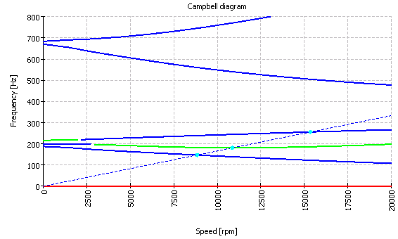
The possibilites for generating a Campbell Diagram had been extended in the shaft calculation. Here a simple rotor with ball bearings under pretension as an example.
The calculation considers natural frequencies for torsion and in axial and radial direction. These are marked in different colors in the Campbell diagram. (Red: Torsion, Green: Axial, Blue: Radial). In the example one mode changes from axial to radial as main component. The axial and radial movements of the shaft are coupled because of the ball bearings which are under pretension in this case. Critical speeds can be marked with an additional point.


