In calculations for shaft systems like gearboxes the shaft are often considered as one-dimensional elements for the calculation of shaft strength, bearing life and safety factors for gears. This has the advantage of short calculation time and easy consideration of boundary conditions. An additional housing stiffness can easily be added by using a stiffness matrix which couples the stiffness at different support positions.
The MESYS shaft system calculation software allows the import of 3D-housings as STEP-files since 2016. The software meshes the parts automatically and generates the reduced stiffness matrices which had to be calculated by separate FEA calculations and then to be imported before.
In version 04/2017 the integration of 3D-elastic parts in the MESYS shaft system calculation is further extended. 3D-elastic housings can not only be considered in a static calculation, but also in the calculation of natural frequencies by using a modal reduction. The influence of housing elasticity on natural frequencies is much larger than on static deformations.
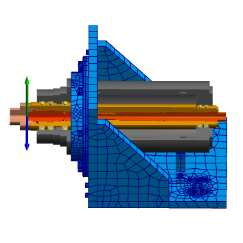
For example a L-shaped spindle test stand without the right support and without considering housing stiffness shows a first natural frequency (an axial mode) of almost 22’000 1/min. Considering the elastic housing the first natural frequency is a bending mode of about 15’200 1/min, which would lead to problem for a planned operating speed of 15’000 1/min. Including the additional right support the natural frequencies of the bending modes rise to 25’000 1/min, die first axial frequency falls to 19’600. The imported CAD-model was the existing CAD-model for manufacturing. This is not optimal because of many holes and the bolts, but it still can be used. In case the holes and bolts are deleted in the CAD-model memory usage and initial calculation time for the calculation can be reduced.

Spindle test stand with elastic housing (Video)
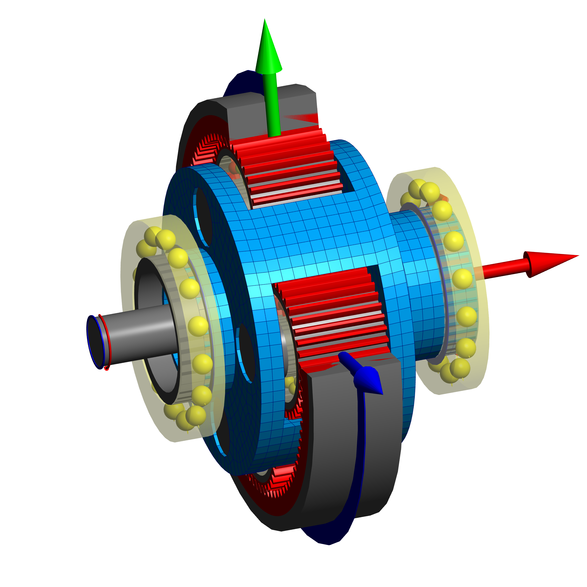
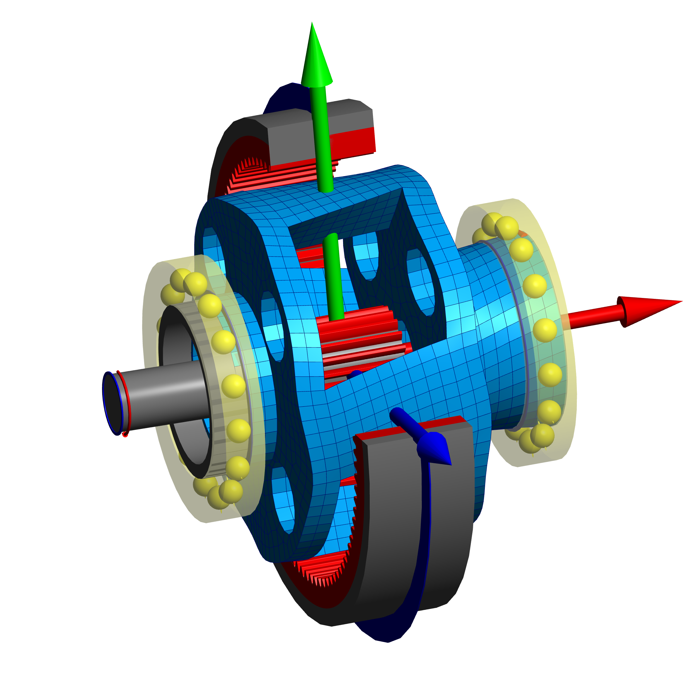
A further extension is the support of 3D-elastic planet carriers. Compared to housings the planet carries rotate in the system and therefore the calculation has to cope with large rotations. The elastic deformations of the planet carries have an influence on the load distribution of the gears and therefore should be considered at design of tooth trace corrections. The tilting of the planets will also have an influence on the bearing loads and the global torsional stiffness.
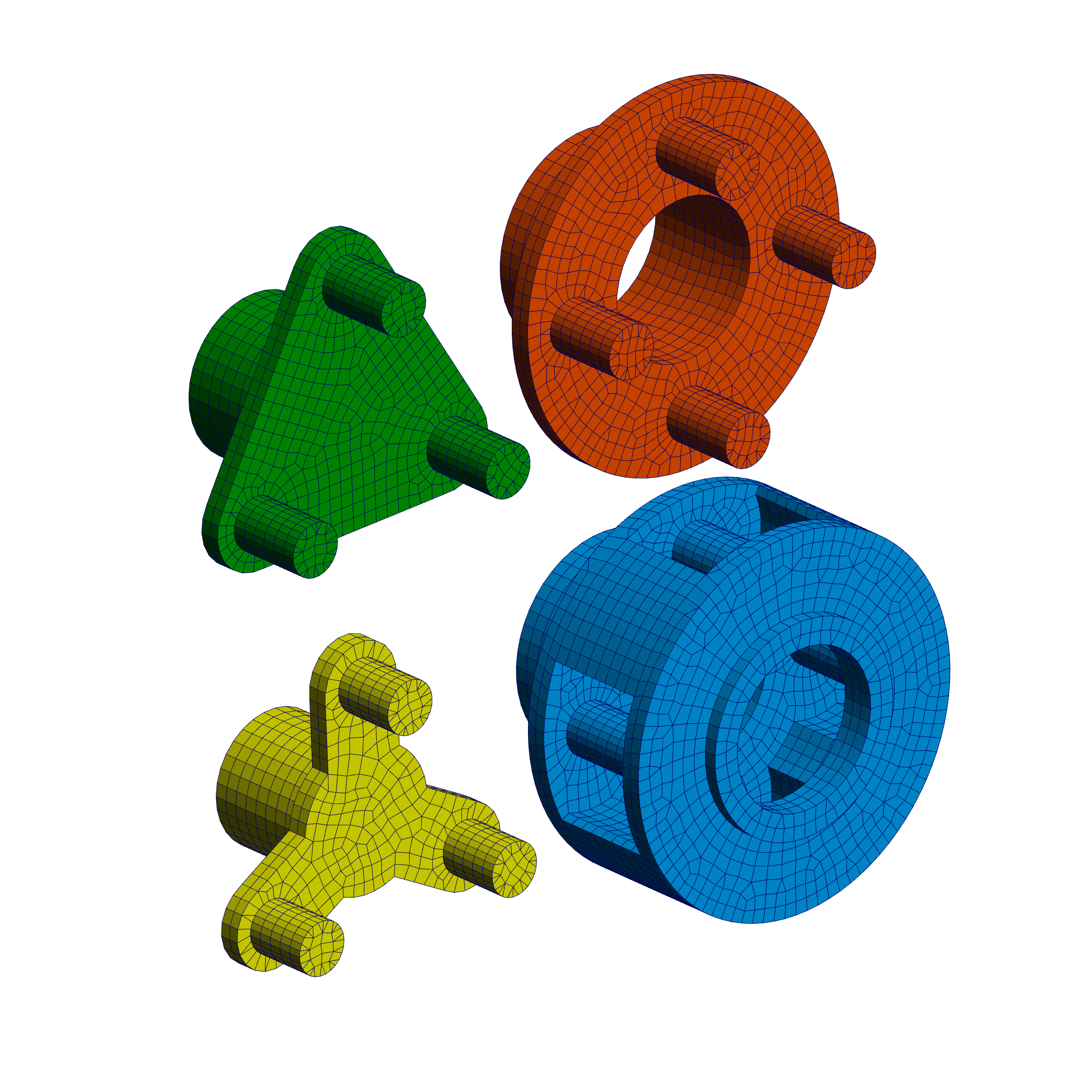
Planet carriers can be imported as CAD-model or be defined parametrically. Four basic variants are available for the parametric planet carriers.
Another possibility of an integration of 3D-elastic parts in the shaft calculation is the option of 3D-elastic rotation symmetric parts, which can be defined using a polygon. These 3D-elastic parts define an additional stiffness matrix. As example a flex-pin is considered here. In some older literature equations for the deformations of a flex-pin are given based on the Euler-Bernoulli-beam without consideration of shear deformations. In an example a beam model without shear deformations shows a deflection of 15µm, including shear deformations the deflection is 23µm and in case of usage of 3D-elastic parts the deflection is 42µm. The usage of a 3D-elastic parts will lead to an increase by 80% compared to a shear-elastic beam element. The reason is the deformation in the two interference fits where the rigid connection of the beams is much too stiff. The 3D-elastic part is providing a better model for the deformations. As the parts are taken into account like welded in the calculation the real-life deformation should still be a little larger as there could be some sliding in the interference fit.
The integration of 3D-elastic parts into the shaft system calculation allows to consider additional stiffnesses without the need of external FEA programs. A time-consuming and error-prone transfer of stiffness matrices is therefore not needed any more.
A full calculation in a FEA program would allow more possibilities for defining boundary conditions and would allow nonlinear calculation including contact. The shaft system calculation based on one dimensional shafts has the main advantage of short calculation time in range of seconds, which allows the use of extensive load spectra and parameter variations. With the integration of 3D-elastic parts these advantages are preserved.


