A new version of the MESYS shaft and rolling bearing analysis software including new functionality is available. The bearing analysis software allows the calculation of the load distribution within the bearing and bearing life according to ISO/TS 16281 and it is integrated in a shaft system calculation with additional possibilities like modal analysis, strength calculation for shafts and interfaces to gear calculations. Currently the software is used by customers in 32 countries on 4 continents. The new version is now available under Downloads.
General Extensions
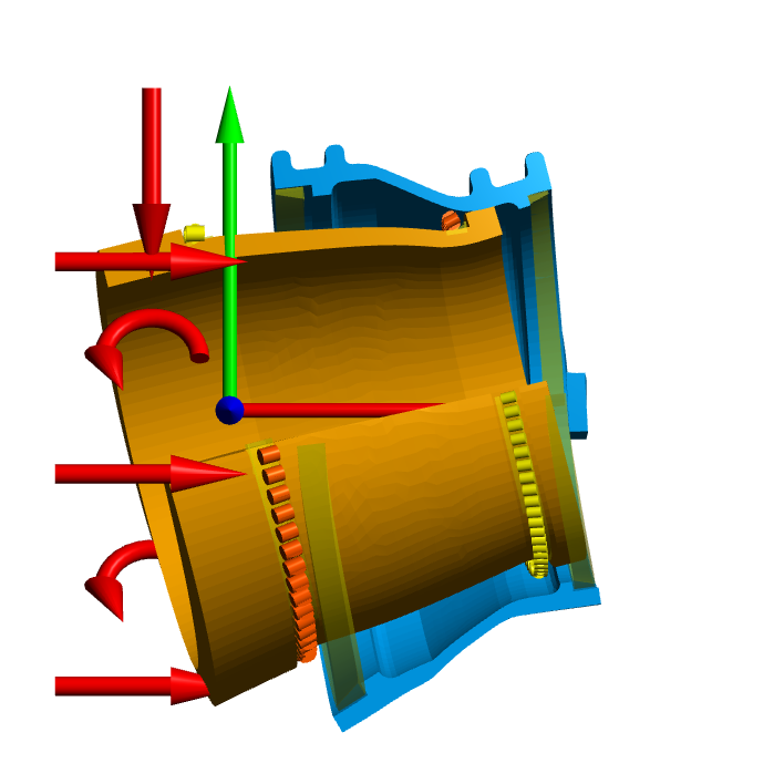
Visualization of 3D-Graphics is now done using OpenGL 4 which allows to draw curves shapes. Cylinders for shafts or 3D-meshes with quadratic elements can now be shown including the curves shapes.
The bearing databases from SKF and NSK are updated. They include only catalog data. A new bearing database from Napoleon Engineering Services is added and includes encrypted internal geometry for split inner ring three point bearings. The databases from CSC and HQW/Barden containing internal geometry are unchanged to the previous version. Additional encrypted databases containing internal geometry are available from GMN, IBC, SPL and GRW, but have to be requested from the manufacturer.
In the status bar of the software a new switch showing ‘M’ or ‘A’ was added, which allows an automatic run of the calculation after each change of inputs. All results including graphics are updated. This allows to see quickly what effect variations have on the results.
In the statistical parameter variations in addition to the diagrams for probability distributions now also cumulative distributions are shown.
Extensions in the Bearing Calculation
The bearing databases can now include values for preload forces for up to four preload classes for angular contact bearings. Several new diagrams are added like for contact dimension showing half axes and areas for contact ellipses and for film parameter and lubricant film thickness. The multi-layer interference fit now also includes tolerances instead of a single value for interference.
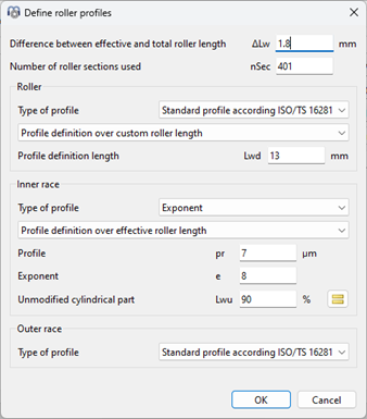
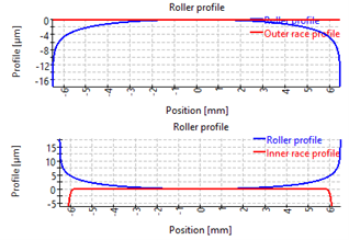
Until now the profiles for rollers and races had to be defined over the same effective roller length. Now the profiles for rollers and races can be defined over different length between effective and total roller length. This allows to take undercut into account on one raceway and a longer contact length on the second raceway.
Extensions in the Shaft Calculation
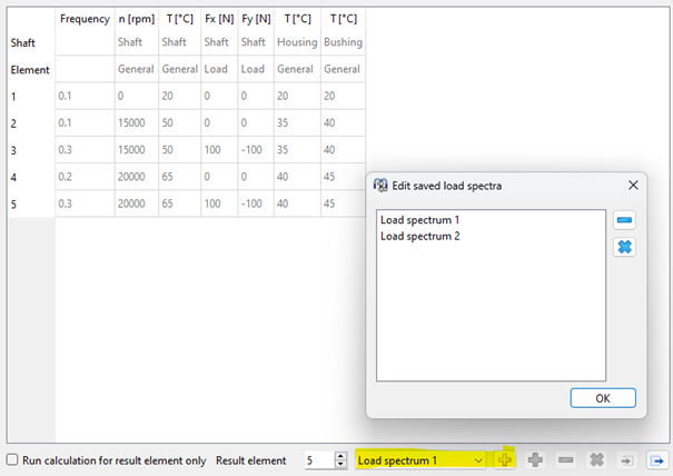
In the shaft calculation now several load spectra can be defined and easily selected for the calculation.
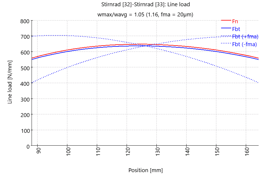
The line load distribution of cylindrical gears is dependent on misalignments in the system. It can be flank line deviations of the gears or parallelism errors of the shafts. These errors can be defined in the system and evaluated with the full system. This is also the most accurate approach. A simplified approach can be used like ISO 6336 method B for face load factor, where the misalignments are only considered in the gear contact and not on the shaft deflections. The line load is calculated with an additional misalignment ‘fma’ considering only the gear mesh stiffness with constant tilting angles of the gears.
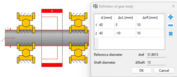
A shaft is stiffened by a gear body and the gear body geometry also affects the line load distribution in the gear contact. The two options for stiffening of the shaft by the gear are extended to five options now and can use a 3D-FEA mesh to consider the gear body stiffness. A simple rotation symmetric gear body geometry can now be defined at the load element, for complex geometries still the 3D-elastic parts option can be used.
For sections on the shaft previously six stiffness values were provided for the three displacements and three rotations. Now full stiffness and compliance matrices are available in the result tables. In addition to cut views with a quarter cut-out now also a 180° cut-out is possible and custom cut directions can be defined for imported housings. A cut-view of imported 3D-elastic parts is now also shown in the 3D-views.
The CAD-Import for 3D-elastic parts now saved the imported STEP file within the calculation. It will then be used for remeshing and for 3D-export of the system. To reduce the file size or to avoid sharing the CAD file, the saved CAD file can be removed under settings of the 3D-elastic part.
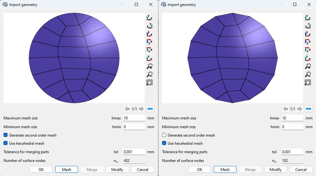
The surface mesh can be generated as a second order mesh on the CAD import now. This improves the accuracy if a second order mesh is selected for calculation afterwards. All nodes will then be on a cylinder, not only the corner nodes of the elements. The disadvantage is the increased file size. A second order mesh requires four times the size of a linear mesh. For large element sizes the outside geometry still looks like a circle instead of a polygon in case of a second order mesh generated on the import.
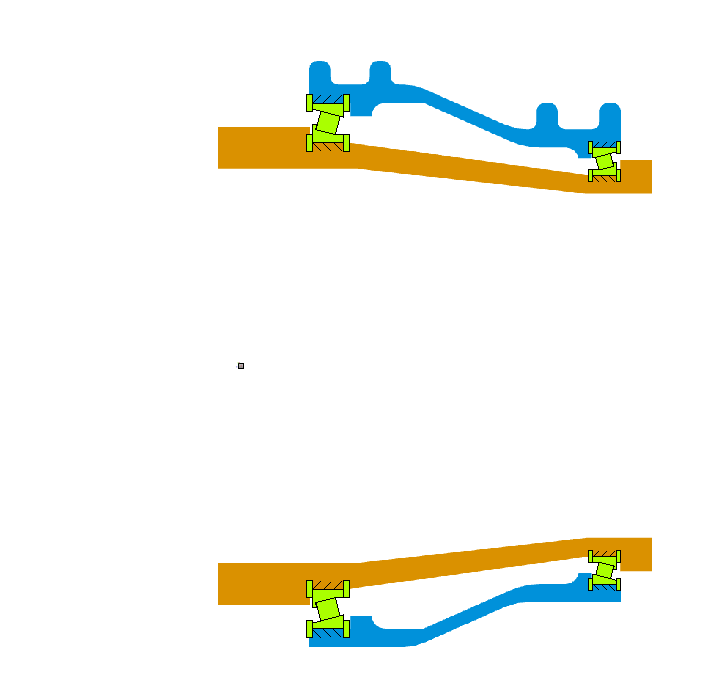
A 3D-elastic part can now be connected to an 1D-shaft using elastic surfaces instead of just using connections by central nodes. For bearings with elastic rings on a 3D-elastic parts also additional axial contacts are considered using elastic faces instead of central nodes.


